|
Contents
User instructions
Purpose of the document
Direction indication in the operating instructions
Images used
General safety instructions
Obligations and responsibilities
Warning Symbols
Organizational events
Safety and security equipment
Private precautions
Staff training
Precautions under normal operating conditions
Danger from residual energy
Preventive maintenance, troubleshooting
Changes to the design
Spare and wear parts and auxiliary materials
Cleaning and disposal
Operator workstation
Warning signs and other symbols used on the machine
Placement of warning signs and other symbols
Danger if the safety instructions are not followed
Working in a safe manner
Safety instructions for the operator
General safety and accident prevention regulations
Hydraulic system
Electrical system
Trailed units
Power take-off operation
Braking system
Tires
Seeder operation
Maintenance, preventive maintenance and care
Loading and unloading
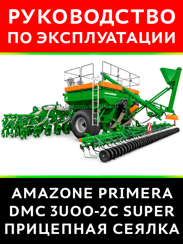
Product description
Browse nodes
Safety and security equipment
Overview of power lines between tractor and implement
Transport and technical equipment
Intended use
Hazardous areas and areas
Type plate and CE mark
Specifications
Necessary tractor equipment
Noise production data
Design and function
How it works
Hydraulic connections
Installation of hydraulic hose lines
Dismantling the hydraulic hose lines
Dual-line service brake system
Connecting the brake line and supply line
Disconnecting the brake line and supply line
Parking brake
Folding chocks
Safety chain for implements without braking system
Stepless gearbox
Dispenser
Metering Coils
Drive wheel
Tray
Fertilization
Seed path - fertilizer path
Fertilization (optional for standard 18.75 cm row spacing)
Overview of disabled coulters and closed outlets in the distributor
Fan
Chisel openers
Protection against collision with a stone
Exact aligner
Harrow harrow with roller (option)
Stony soil rollers (optional)
Support
Bunker with folding tarpaulin
Maintenance platform with ladder
Level sensor
Camera system
Work lighting
Loading auger (optional)
Distributor head and tramline device
Tramline rhythm
Tramline marker (optional)
AMALOG +
Front bogie
Commissioning
Checking the suitability of the tractor
Calculation of the actual parameters of the total weight of the tractor, loads on the tractor axles and tires, as well as the required minimum load
Operating conditions of the tractor with the attached machine
Units without their own braking system
Securing the tractor / machine against unintended starting and rolling
Coupling and uncoupling the machine
Attaching / detaching the trailed cross member
Attaching / detaching the towing eye / ball
Maneuvering with the implement uncoupled
Settings
Dosing roller selection
Selection table for metering rollers according to seed
Level sensor adjustment
Dismantling / mounting the dosing roller
Application rate adjustment on the gearbox
Seeding / Fertilizing Rate Control
Determining gearbox position using a logarithmic disk
Setting the fan speed
Fan speed table
Setting the fan speed with the pressure limiting valve of the der Maschine unit
The fan speed is displayed on the on-board computer display
Adjusting double discs
Leveler adjustment
Transportation
Move machine to transport position
Unit operation
Filling the seed hopper
Filling the hopper with a filling auger
Putting the machine into working position
Sowing
Headland
Unloading the batcher or hopper and batcher
Faults
Dosing system errors
Maintenance, preventive maintenance and care
Cleaning
Cleaning the distributor head (specialist workshop)
Instructions for lubricating the machine (specialist workshop)
Lubrication points overview
Drill roller bearing
Axle lubrication
Maintenance plan - overview
Axle and brake
Parking brake
Checking the towing hitch
Tires / wheels
Tire pressure
Mounting tires
Hydraulic system
Hydraulic hose line markings
Maintenance intervals
Inspection criteria for hydraulic hose lines
Installation and removal of hydraulic hose lines
Upper and lower link pins
Setting the tramline to the track width of the tractor (specialist workshop)
Setting the track width (activating and deactivating the shutters)
Liquid level control in a continuously variable gearbox
Hydraulic diagram
Bolt tightening torques |
 Haynes Manual")

 Translation Techniques. English - Russian. Практические основы перевода
Автор: Т. А. Казакова
Год издания:

 Fiat Grande Punto / Grande Punto Sport / Abarth Super Sport с 2005 года, книга по ремонту в электронном виде
Автор: Монолит
Год издания: