|
Content
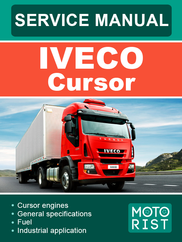
Cursor engines F3A
General specifications
Correspondence between technical and commercial codes
Views of the engine(only for type F3AE0684P*E904)
Views of the engine (for types: F3AE0684P*E906 -F3AE0684L*E906 - F3AE0684P*E905)
Views of the engine (only for type: F3AE0684N*E907)
Views of the engine (only for type: F3AE0684N*E907)
Lubrication diagram(only for type: F3AE0684P*E904 )
Lubrication diagram (for types: F3AE0684P*E906 - F3AE0684L*E906 - F3AE0684P*E905)
Lubrication diagram (engines F3AE0684N*E907)
Oil pump
Overpressure valve
Oil pressure control valve
Heat exchanger (for type: F3AE0684P*E906 - F3AE0684L*E906 - F3AE0684P*E905 - F3AE0684N*E907)
Heat exchanger(only for type: F3AE0684P*E904)
By-pass valve
Thermostatic valve
Engine oil filters
Cooling
Water pump
Thermostat
Turbocharging
EGR exhaust gas recirculation system
Internal EGR acting on the intake valves
Fuel
Feeding
Fuel supply diagram (all types)
Fuel pump
Injector-pump
Industrial application
Clearance data
Mechanical components
Engine disassembly assembly
Engine assembly
Engine flywheel
Fitting engine flywheel
Fitting camshaft
Fitting pump-injectors
Fitting rocker-arm shaft assembly
Camshaft timing
Phonic wheel timing
Intake and exhaust rocker play adjustment and pre-loading of rockers controlling pump injectors
Engine completion
Electrical equipment
Components on the engine F3A (For all types except F3AE0684P*E904)
Components on the engine F3A (only for type F3AE0684P*E904)
Components on the engine F3A (only for type F3AE0684N*E907)
Components on the engine F3A (only for type F3AE9687A*E001)
Block diagram
EDC 7 UC31 electronic control unit
EDC control unit PIN-OUT
Pump injector
Engine coolant temperature sensor
Fuel temperature sensor
Flywheel pulse transmitter
Distribution pulse transmitter
Alternator
Starting motor
Pre/post-heating resistance
EDC system functions
Troubleshooting
Preface
Methods of diagnosis
PT-01 Portable tester
Main functions
Test parameters
Failure codes
Overhaul and technical specifications
General characteristics
Assembly clearance data
Engine overhaul
Engine removal at the bench
Repair operations
Cylinder block
Checks and measurements
Cylinder liners
Replacing cylinder liners
Crankshaft
Measuring the main journals and crankpins
Preliminary measurement of main and big end bearing shell selection data
Selecting the main and big end bearing shells
Replacing the timing gear and oil pump
Checking main journal assembly clearance
Checking crankshaft end float
Assembling the engine on the bench
Piston connecting rod assembly
Piston rings
Connecting rods
Bushings
Checking connecting rods
Mounting the piston rings
Fitting the big end bearing shells
Fitting connecting rod - piston assemblies in the cylinder liners
Checking piston protrusion
Checking crankpin assembly clearance
Cylinder head
Removing valves
Checking the planarity of the head on the cylinder block
Removing deposits and checking the valves
Valves
Valve seats
Checking clearance between valve-stem and associated valve guide
Valve guides
Replacing injector cases
Checking injector protrusion
Timing gear
Camshaft drive
Idler gear pin
Idler gear
Twin intermediate gear pin
Twin idler gear
Replacing the bushings
Camshaft
Checking cam lift and pin alignment
Camshaft
Bushings
Valve springs
Fitting valves and oil seal
Rocker shaft
Shaft
Rocker arms
Tightening torque
Tools
Appendix
Safety prescriptions
Standard safety prescription
Prevention of injury
During maintenance
Respect of the environment
F3B cursor engines
General specifications
Correspondence between technical code and commercial code
Views of engine (for types: F3BE0684H*E901 - F3BE0684G*E901)
Views of engine (only for type F3BE0684J*E902)
Views of engine (only for types: F3BE9687A*E001 - F3BE9687B*E001 - F3BE9687C*E001)
Lubrication diagram (only for types F3BE0684J*E902 - F3BE9687A*E001 - F3BE9687B*E001 - F3BE9687C*E001)
For types: (F3BE0684G*E901 - F3BE0684H*E901)
Oil pump
Overpressure valve
Oil pressure control valve
Heat exchanger
By-pass valve
Thermostatic valve
Engine oil filters
Cooling
Water pump
Thermostat
Turbocharging
EGR Exhaust gas recirculation system (only for F3BE0684J*E902)
Internal EGR acting on the intake valves early closing system for the intake valves (”miller” cycle) - (for types F3BE0684H*E901 - F3BE9687A*E001 - F3BE9687B*E001 - F3BE9687C*E001)
Fuel
Feeding
Fuel supply diagram
Injector-pump
Fuel pump
Industrial application
Clearance data
Mechanical components
Assembling and disassembling the engine
Engine assembly
Engine flywheel
Fitting engine flywheel (For types: F3BE0684H*E901 - F3BE0684G*E901)
Fitting engine flywheel (For types: F3BE0684J*E902 - F3BE9687A*E001 - F3BE9687B*E001 - F3BE9687C*E001)
Fitting camshaft
Fitting pump-injectors
Fitting rocker-arm shaft assembly
Camshaft timing
Phonic wheel timing
Intake and exhaust rocker play adjustment and pre-loading of rockers controlling pump injectors
Engine completion
Electrical equipment
Components on the engine F3B (For types: F3BE0684H*E901 - F3BE0684G*E901)
Componenti sul motore F3B (Only for type: F3BE0684J*E902)
Componenti sul motore F3B (F3BE9687A*E001 - F3BE9687B*E001 - F3BE9687C*E001)
Block diagram
EDC 7 UC31 electronic control unit
EDC control unit PIN-OUT
Injector pump
Engine coolant temperature sensor
Fuel temperature sensor
Flywheel pulse transmitter
Distribution pulse transmitter
Alternator (For types: F3BE0684H*E901 - F3BE0684G*E901)
Alternator (For type: F3BE0684J*E902)
Alternator (For types: F3BE9687A*E001 - F3BE9687B*E001 - F3BE9687C*E001)
Starting motor
Pre/post-heating resistance
EDC system functions
Troubleshooting
Methods of diagnosis
PT-01 preface
PT-01 portable tester
Main functions
Test parameters
Failure codes
Overhaul and technical specifications
General characteristics
Assembly clearance data
Engine overhaul
Engine removal at the bench
Repair operations
Cylinder block
Checks and measurements
Cylinder liners
Replacing cylinder liners
Removal
Assembly and checking protrusion
Crankshaft
Measuring the main journals and crankpins
Preliminary measurement of main and big end bearing shell selection data
Selecting the main bearing and big end bearing shells
Replacing the timing control gear and the oil pump
Checking main journal installation clearance
Checking crankshaft end float
Assembling the engine on the bench
Diagram showing the underblock fixing screws tightening order
Piston connecting rod assembly
Removal
Measuring the diameter of the pistons
Conditions for correct gudgeon pin-piston coupling
Piston rings
Connecting rod
Checking connecting rod alignment
Mounting the connecting rod - piston assembly
Mounting the piston rings
Fitting the connecting rod-piston assembly into the piston liners
Piston protrusion check
Checking assembly clearance of big end pins
Cylinder head
Valve removal
Checking the planarity of the head on the cylinder block
Removing deposits and checking the valves
Valve
Valve guides
Replacing of valve guides
Replacing - reaming the valve seats
Replacing injector holder cases
Checking injector protrusion
Camshaft
Checking cam lift and pin alignment
Bushings
Replacing camshaft bushes using beater 99360499
Valve springs
Fitting the valves and oil seal ring
Rocker shaft
Shaft
Rocker
Timing gear
Camshaft drive
Idler gear pin
Idler gear
Twin intermediate gear pin
Twin idler gear
Replacing the bushings
Tightening torque
Tools
Appendix
Safety prescriptions
G-Drive cursor engines
General specifications
Correspondence between technical code and commercial code
Views of engines
Lubrication
Cooling
Description
Operation
Fuel feed
F2B engine fuel supply pump
Turbocharging
G-Drive application
F3A engine clearance data
F3B engine clearance data
F3A general characteristics
F2B assembly clearance data
F3B general characteristics
F3B assembly clearance data
Engine connection and disconnection from the radiator
Engine assembly / disassembly
F2B engine disassembly
F2B engine assembly
F3B engine disassembly
F3B engine assembly
Maintenance planning
Recovery
Inspection and/or maintenance interventions
Checks not included in maintenance planning-daily checks
Maintenance procedures
Checks and controls
Principle electrical diagram
Key to components
Function symbols for the control panel
Engine interface box
Connectors |
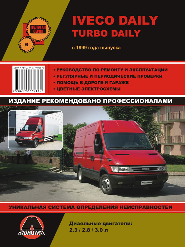
 Iveco Daily / Iveco Turbo Daily с 1999 года, книга по ремонту в электронном виде
Автор: Монолит
Год издания:


