|
|
Content
General information
Vehicle identification
Identification code
Models complete set
Lubricants and special fluids. Refueling volumes
Engine
Engine view from different sides
Datasheet
Performance charts
General characteristics
Nominal sizes and fits of mating parts
Troubleshooting
Diagnostic devices
Troubleshooting
Tightening torques
Diagrams of the sequence of tightening the bolts of fastening of the main engine components
Tools and equipment
Removal and engine installation
Dismantling the engine at the stand
Repair
Assembling the engine at the stand
Flywheel
Lubrication system
Cooling system
Turbocharging system
Turbocharger HOLSET HY55V
Turbocharger HOLSET HX 50W
Power system
HIDROCAR power take-off on the gas distribution mechanism (optional)
Clutch
Description
Specifications
Troubleshooting
Tightening torques
Tools and equipment
Removing and installing clutch
Checking
Removing and installing bearing
Clutch release
Clutch release drive (for vehicles with gearboxes ZF 16 S 151/181/221 O.D.)
Removing and installing the pedal unit
Pedal unit
Dismantlingcassembling the pedal unit
Checking and adjusting the clutch pedal travel stops (for vehicles with gearboxes ZF 16 S 151/181/221 O.D.)
Hydraulic clutch drive (for vehicles with gearboxes ZF 16 S 151/181/221 O.D.)
Clutch slave cylinder for gearboxes ZF 16 S 151/181/221 O.D
Bleeding hydraulic clutch actuator
Clutch slave cylinder for gearbox EUROTRONIC 16 A S 2601 O.D.
Gearbox
Gearboxes ZF 16 S 151/181/221 O.D
Gearboxes ZF 16 S 151/181/221 O.D. with hydraulic retarder
Gearbox EUROTRONIC 16 AS 2601 O.D
Gearbox EUROTRONIC 16 AS 2601 O.D. with hydraulic retarder
Hydraulic retarder
Location of the hydraulic retarder identification plate
General information
How it works
Location of the main units of the retarder
Removing and installing retarder on gearbox ZF S 151/181/221 O.D.
Specifications
Tightening torques
Tools and equipment
Troubleshooting
Repair of the hydraulic retarder
Power take-off
Description
Specifications
Tightening torques
Tools and equipment
Removal-installation of the power take-off
Power take-off repair
Transfer cases and differentials
Description of transfer case TC 1800 and TC 2200
Specifications
Version with power take-off (order number 391.392)
Power take-off specifications
Using the transfer case
Transfer case differential
Tightening torques
Tools and equipment
Lubrication system
Removing and installing transfer case
Disassembly of the transfer case at the stand
Cleaning and checking parts
Replacing the oil seals in the output shaft cover
Cardan shafts
Specifications
Troubleshooting
Tightening torques
Tools and equipment
Removing and installing propeller shaft
Cardan shaft repair
Checking cardan shafts on a car
Bridges
Troubleshooting
Removing-installing rear axle
Front axle 5985 / 2D (D1385)
Middle bridges 452191 / 2D (R9274) 453291 / 2D (R9189)
Middle bridge 452146 / 2D (R 9174)
Rear axles 451391 / 2D (R 8284) 452191 / 2D (R 8274) 453291 / 2D (R 8298)
Rear axle 452146 / 2D (R 8174)
Twin bridges MERITOR RT 153E / 2D center axle RP 153E
Rear axle RR 167E
Front and rear suspension
Front and rear leaf springs
Specifications
Front shock absorbers
Rear shock absorbers
Pneumatic suspension
Specifications
The main components of the pneumatic system
Troubleshooting
Tightening torques
Tools and equipment
Removal-installation of front axle leaf springs
Removal-installation of leaf springs of the intermediate (second) axle (8 ? 4 vehicles)
Removal-installation of leaf springs of the rear axle (cars 4 ? 2 - 4 ? 4)
Removal-installation of leaf springs of rear balance suspension (vehicles 6 ? 4 - 6 ? 6 - 8 ? 8)
Rear balancer suspension (vehicles 6 ? 4 - 6 ? 6 - 8 ? 4 - 8 ? 8)
Removal-installation of the reaction rod of the balance suspension of the rear axle
Removalqinstallation of the reactive bar of the balancer suspension of the intermediate axle
Removalqinstallation of the vq-shaped arm of the rear axle of cars with air suspension
Replacing Throttle / V-Arm Pivot Pins
Shock absorbers
Anti-roll bars
Anti-roll bar
Front axle anti-roll bar
Trailing axle anti-roll bar (8 ? 4 vehicles)
Rear axle anti-roll bar
Intermediate axle anti-roll bar (vehicles 6 ? 4 - 6 ? 6 - 8 ? 4 - 8 ? 8)
Wheels and tires
Specifications
Description
Tools and equipment
Troubleshooting
Static wheel balancing
Residual static imbalance correction
Tire pressure
Relationship between tire pressure and wheel behavior when driving
Steering
Description
Completion of vehicles with steering mechanisms
Specifications
Troubleshooting
Tool
Tightening torques
Power steering gear
Disassembly and assembly of the steering column
Basic Operations
Pneumatic system - brakes
Symbols on the schematic diagrams of pneumatic and hydraulic systems (auxiliary equipment and power units)
Symbols on the schematic diagrams of pneumatic and hydraulic systems (valves)
Symbols on the schematic diagrams of pneumatic and hydraulic systems (receivers and energy storage devices)
Symbols on the schematic diagrams of pneumatic and hydraulic systems (transformers, cylinders and calipers)
Symbols on the schematic diagrams of pneumatic and hydraulic systems (calipers and cylinders)
Symbols on the schematic diagrams of pneumatic and hydraulic systems (half couplings and couplings)
Symbols on the schematic diagrams of pneumatic and hydraulic systems (half couplings and couplings)
Symbols on the schematic diagrams of pneumatic and hydraulic systems (control devices and switches)
Symbols on the schematic diagrams of pneumatic and hydraulic systems (brakes)
Tubes and fittings
Braking system
Body and chassis
Cab
Tightening torques
Tools and equipment
Cab fixing
Repair
Replacing the front and rear cab suspension shock absorbers
Removing and installing the front cab mount and its stabilizer
Replacing the cab tilt cylinder
Windshield replacement
Replacing the sliding door glass
Replacing the power window drive mechanism
Replacing a fixed door glass
Roof hatch replacement
Driver's cab ventilation and heating
Car frame
Inspection and repair work
Safety instructions
Scheduled maintenance
Scheduled maintenance
Additional work
Inspection and / or maintenance work
Location of inspection and / or maintenance points
Location of inspection and / or maintenance points
Inspection and / or maintenance work
Maintenance M1
Maintenance M2
Maintenance M3
Maintenance M4 (frequency is measured only in kilometers)
Additional maintenance work
Maintenance EP2
EP3 maintenance
Maintenance EP4
Maintenance EP5 |
 Translation Techniques. English - Russian. Практические основы перевода
Автор: Т. А. Казакова
Год издания:
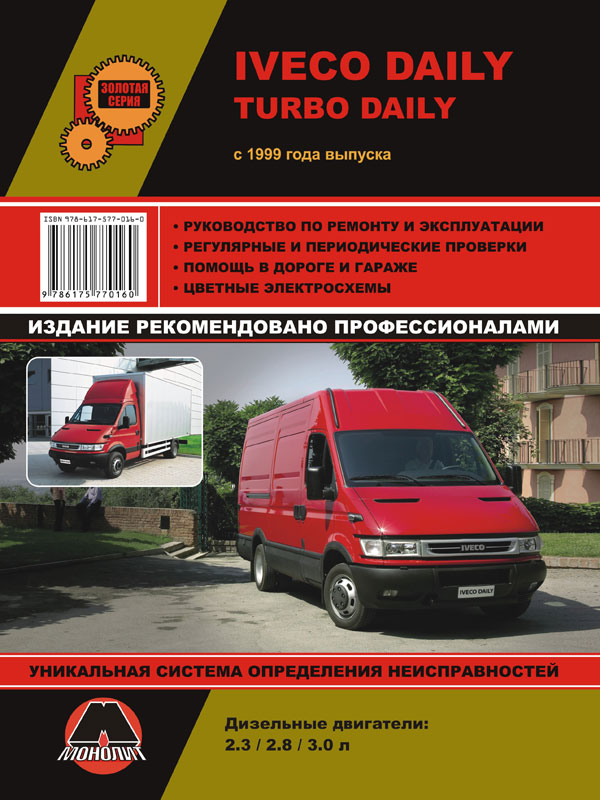
 Iveco Daily / Iveco Turbo Daily с 1999 года, книга по ремонту в электронном виде
Автор: Монолит
Год издания:


