|
Content
Introduction
General precautions when working with electrical / electronic components
Concepts of mass and electromagnetic compatibility
CAN communication line concept
Technical codes
Graphic symbols and abbreviations
General information
Basic system description
Technical and electrical characteristics
Cabin arrangement
Engine device
Frame device
Cab tilted
Interior of the car
Power network
Negative chain
Ground points
Positive chain
Launch
Main components
Main control unit
Dashboard and instrument groups
Starter
Generator
Lever steering wheel
Ignition lock
Engine control unit (ECU)
Front connector
Rear connector
Cable connector codes (ST)
Special electrical circuits
ABS / EBS
Description and principle of operation
Components
APU (Air handling unit)
ASR (Traction control)
EBL (Electronic brake force limiter)
ABS (Anti-lock braking system)
Pin assignment of the ABS control unit
EBS (Electronic braking system)
The main components of the EBS system. Duplex distributor with electrical converter
Front axle proportional control valve
Front axle ABS solenoid valves
Electro-pneumatic rear axle modulator
Trailer brake servo valve
Diagnostics
Diagnostics with MODUS
Diagnostics with UNITESTER
Diagnostics with IWT (Iveco electrical equipment tester)
Repair operations
Troubleshooting
EDC MS6.2
Description and principle of operation
EDC control unit
Location and identification of EDC MS6.2 system components
Components
Pressure sensor
Fuel temperature sensor
Boost pressure sensor
Coolant temperature sensor
Manifold air temperature sensor
Diagnostics
Connecting to the EDC control unit wiring for the engine (a) and the cab / frame (b)
Troubleshooting procedure
Engine brake
ECAS
Description and principle of operation
Location of components in the cab of EuroTech / EeuroStar cars
Electrical wires in the car
Electronic control unit ECAS (ECU)
Main components of the system
Level sensor
Axle load limiting valve
Air suspension low pressure sensor
Signal booster
Electro-pneumatic valve
Electro-pneumatic axle valve "9820" / "78242"
Electro-pneumatic valve "9838" / "78243"
Electro-pneumatic distributor of the rear axle "9838" / "78243"
Electro-pneumatic distributor of the rear axle "9838" / "78243"
Electro-pneumatic distributor of the rear axle "9838" / "78243"
Remote control "8568" / "85065"
Axle lifting system
Description and principle of operation
Lowering the frame
Frame alignment
Auxiliary axle control (pneumatic lift system)
Raising an additional bridge
Lowering the additional bridge
Assistance at the beginning of lifting the axle (vehicles with air suspension)
Additional steer axle steering
Location of the main components of the hydraulic system on the vehicle
Functional diagram of the hydraulic system
Calibration of the electronic control unit
Electronic control unit programming
Diagnostics
System diagnostics
Repair operations
Activating and reading flashing code
Immobilizer
Description and principle of operation
System features
Components
Electronic control unit "immobilizer"
li>
Electronic control unit "immobilizer"
Antenna
Ignition lock
Control lamp
Electronic keys (2 pcs.)
Code card
Component locations - cable routing
Emergency start procedure
Diagnostics with MODUS
Diagnostic connector
Wiring diagrams
Conventions
Scheme №1: starting the engine from the driver's seat
Scheme №2: starting from the engine compartment
Scheme №3: warming up
Scheme №4: charging
Scheme №5: instruments (fuel level - coolant temperature and voltmeter)
Scheme №6: instruments (pressure in the engine lubrication system and air pressure in the pneumatic drive of the brakes)
Scheme №7: devices (tachograph - tachometer)
Scheme №8: control lamps
Scheme №9: side lights (inside the cab)
Scheme №10: side lights (outside the car)
Scheme №11: low and high beam headlights
Scheme №12: additional headlights and rear fog lights
Scheme №13: direction indicators and hazard warning lights
Scheme №14: brake lights - reversing lights - sound signal
Scheme №15: windshield wiper
Scheme №16: interior lighting and auxiliary equipment
Scheme №17: rear-view mirrors on the car wings
Scheme №18: electric windows
Scheme №19: basic anti-lock braking system ABS
Scheme №20: electronic braking system EBS
Scheme №21: EDC diesel engine electronic control unit
Scheme №22: EDC (connector a)
Scheme №23: vehicles equipped / not equipped with a power take-off and CAN |
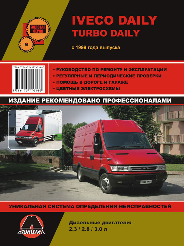
 Iveco Daily / Iveco Turbo Daily с 1999 года, книга по ремонту в электронном виде
Автор: Монолит
Год издания:
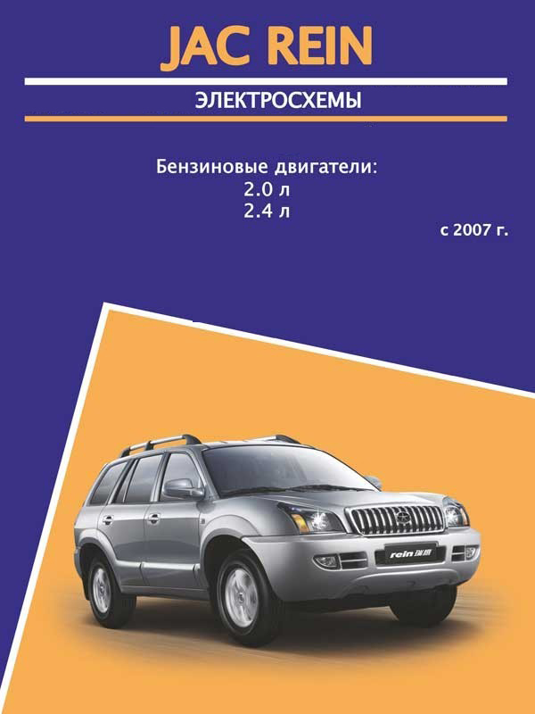
 JAC Rein since 2007, wiring diagrams and connectors in electronic form
Автор: Авторесурс
Год издания:
 Suzuki New SX4 / SX4 S-Cross from 2013 year of release, wiring diagram in electronic form
Автор: Монолит
Год издания:
