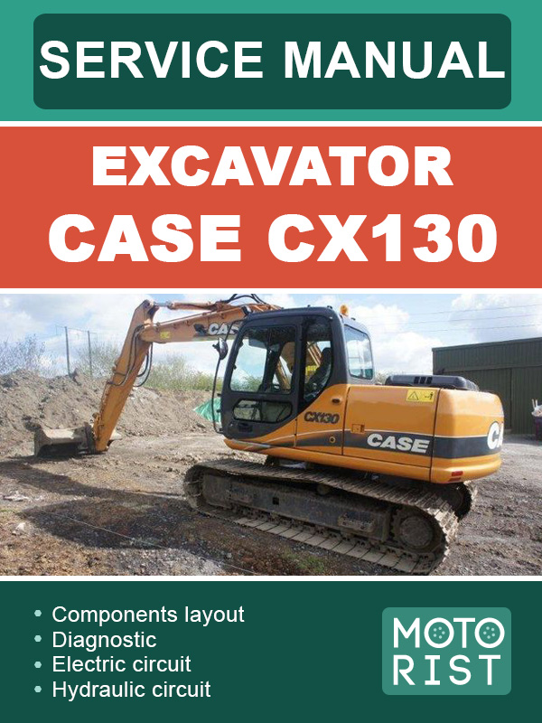
|
Content
General information
Safety
Standard torque data for cap screws and nuts
Type, serial number and year of manufacture of the machine
Fluids and lubricants
Special torque settings
Machine overall dimensions
Components layout CX130
General layout
Electrical component layout of the upper chassis
Electrical component layout of the cab
Cab controls
Instrument panel
Components CX130
Hand remote controls
Travel foot controls
Auxiliary foot controls
Cushion valve
Main hydraulic pump
Pilot pressure gear pump
Proportional solenoid valve
Control valve
Boom safety valve
Dipper arm safety valve
Dual flow valve
Swing motor
Drive motor
Swivel joint
Flow restrictor
Boom cylinder
Solenoid valve block
Diagnostic - selection
Access and contents of control screens
Warning messages
Excavator model selection procedure
Changing the language code
Anti-theft device
Changing the access code for the anti-theft system
Troubleshooting
Electrical inspection of components
Electric circuit
General location of components
Relays and main fuses
Fuse box
Instrument panel
Engine control
Working mode selection
H / S / L mode control
Automatic mode control
Acceleration control
Control of engine return to idle
Hammer mode control
Automatic engine pre-heat
Automatic engine warm-up
Engine emergency stop
Emergency mode
Locking functions
Power boost
Swing brake
Travel speed
Supply cut-off delayed
Water temperature gauge
Hydraulic oil temperature gauge
Fuel level
Engine fuel injection pump electronic regulator
Electric circuit
High speed travel circuit
Low speed travel circuit
Straight travel circuit
Swing operation, swing parking circuit
Swing priority variable throttle circuit
Boom up 2 speed circuit
Boom down load holding valve circuit
Arm out 2 speed circuit
Circuit for breaker and crusher
Pump CX 130
Hydraulic pressure settings
Special tools
Identification of hydraulic components
Preparation before inspection
Checking and pressure setting procedure
Troubleshooting |


