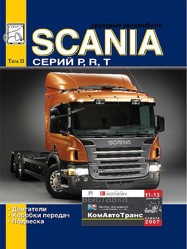
 Scania P / R / T with engines of 9.0 / 11.0 / 12.0 / 14.0 / 16.0 liters, service e-manual (in Russian), volume 2
Автор: Диез
Год издания: 0000
The second volume provides information on:
- engine repair
- gearbox repair
- suspension repair
Content
Engine
Accessory belt drive
9-liter engine
11-liter engine
12-liter engine
Key features
Replacing the engine
Cylinder heads
Cylinder block
Flywheel and flywheel housing
Crankcase ventilation and front crankshaft oil seal
Connecting rod-piston group
Flywheel
Crankshaft
Distribution mechanism
Lubrication system
Turbocharger
Injection equipment and engine speed control
16-liter engine
Technical data
Removing and installing the engine
Cylinder head
Adjusting the unit injectors
Cylinder head machining operations
Replacing the valve guides
Replacing the unit injector sleeves
Cylinder block
Measuring cylinder liner protrusion
Undercutting the cylinder liner seat
Replacing the crankshaft rear oil seal
Removing the camshaft bearing
Installing the camshaft bearings
Flywheel housing removal
Installing the flywheel housing
Removing the front engine cover
Installing the front engine cover
Replacing the front crankshaft oil seal
Removing the crankshaft oil seal cover
Installing the crankshaft oil seal cover
Replacing the plug in the cylinder block
Crank mechanism
Installing the piston
Replacing the piston
Checking the connecting rod
Flywheel
Crankshaft
Camshaft drive gears
Removing the idler gear
Installing idler gear
Replacing the idler gear bearing
Removing the camshaft gears
Installing the camshaft
Removing the crankshaft drive gear
Installing the crankshaft drive gear
Removing and installing camshaft
Checking the installation of the camshaft
Fan drive
Replacing the oil filter
Replacing the oil cooler seal
Heat exchanger installation
Oil pump
Exhaust manifold
Turbocharger
Engine mounts
Attachment drive
Engine cooling system
Fuel system
Description of the fuel system with unit injectors and PDE and EDC MS6 control unit
General information
Fuel system hydraulic diagram
Cyclic fuel supply and injection start moment
Fuel system components
Fuel system layout on engine
Control unit cooler
Fuel rail
Fuel pressure regulator
Unit injector
Fuel filter
Electronic fuel control system st EDC
Elements of the EDC system located on the engine
Elements of the EDC system located at the driver's workplace
Fault code output
Fault codes
Fuel system performance tests
Faults that do not cause trouble codes
Interaction of EDC with other systems
Repair of fuel system with unit injectors and PDE and EDC MS6 diesel engine electronic control system
Unit injectors
Removing the unit injector
Removing the unit injector (16 liter engine, vehicle with T cab)
disassembly of unit injectors
Cleaning the unit injector
Checking the unit injectors
Adjusting the needle lift pressure
Assembly of unit injectors
Solenoid valve
Installing the unit injector
Installing the unit injector (16 liter engine, vehicle with T cab)
Adjusting the pump injector
Unit injector adjustment procedure
Booster pump
Fuel filter
Bleeding the fuel system and measuring the pressure in the system
Electronic diesel control (EDC) electrical cables
EDC control unit
Description of SCANIA HPI fuel system with EDC S6 control unit
General information
Fuel system hydraulic diagram
Cyclic fuel supply and injection advance
Fuel system components
Pump-injector
Electronic fuel control system EDC S6
Elements of the EDC system located on the engine
Elements of the EDC system located at the driver's workplace
Cruise control system controls
Fault indicator and fault codes output
Fault codes
Storing fault codes in the memory of the control unit
Emergency operation
Interaction of the EDC system with other systems
Motor retarder
Hydraulic retarder
Pulse width modulated signals
CAN bus
Repair of Scania HPI fuel system with EDC S6 control unit
General provisions
Removing the unit injector
Installing the unit injector
Adjustment of clearances in the valve mechanism and closing force of pump-injectors
Checking the pressure in the fuel system and the fuel supply
Checking the tightness of the fuel system
Replacing the fuel filter
Installation
Fuel rail, valve block and solenoid valves
Fuel cut-off valve
Fuel lines
Electrical connections on the control unit
Gearboxes (GR801, GR900, GRS890, GRS900, GRS920, GRSH900, GRSO900)
Datasheet
Gearbox GR801
Gearbox GR900
Gearbox GRS900
Gearbox GRS890
Gearbox GRS920
Gearbox GRSO900
How it works
Main gearbox
Input shaft
Axle of the idler reverse gear
Secondary shaft
Intermediate shaft
Synchronizer
Planetary demultiplier
Shift housing cover
Gearshift housing
Demultiplier and Divider
Divider blocking valve
Inductive speed sensor with overspeed protection
Shift Knob
Lubrication system
Gear shifting
Technical data
Repair
Main gearbox
Dismantling the gearbox
Synchronizer
Gearshift housing
Checking the shift pins
Separate assembly operations for GRS gearboxes
Gearbox assembly
Adjusting the bearing clearance
Installing planetary gear
Installing the gearshift housing and gearshift housing
Specification
Dismantling and installation of manual transmissions
Gearbox with torque converter
Cars with all-wheel drive transmission
Transmission with automatic switching system "Opticruise"
Gearbox without hydraulic retarder
Dismantling gearboxes
Draining coolant and oil from hydraulic retarder
Technological engine mounts
Disconnecting the clutch release
Installation of gearboxes
Preparing the clutch for gearbox installation
Filling coolant and hydraulic retarder
Tightening torques
Transmission oil cooler
Replacing the oil cooler for 11 and 12 liter engines
Replacing the oil cooler for a 14 liter engine
Replacing the oil cooler for a 16 liter engine
Checking the tightness of the oil cooler
Shafts of manual transmissions
Dismantling the input shaft
Input shaft assembly
Disassembly of the output shaft
Replacing the splitter gear bearing ring
Output shaft assembly GRS / GRSO / GRSH
Output shaft assembly GR801 / 900
Intermediate shaft of gearbox GR801
Intermediate shaft of the GR900 gearbox
Intermediate shaft of the GRS gearbox
Dismantling the intermediate shaft
Assembling the intermediate shaft
Tightening torques for screw connections
Consumables
Transmission control actuator for P and R series vehicles
Precautions
General information
Design differences
General view of the control drive
Shift lever assembly
Gear shift drive
Support bracket
Check and adjust
Adjustment parameter and tightening torques for threaded connections
Main gear
Datasheet
General provisions
Bevel final drive
Tooth contact pad
Final drive ratio
Bearings
Middle and rear drive axles
Cross-axle differential
Center differential
Differential lock mechanism
How it works
Lubrication system
Repair manual
General information
Compliance with the requirements of cleanliness
Security measures
Disassembled main gear
Adjusting the air-hydraulic pump to a given force
Oil
Replacing the universal joint yoke lip seal
Dismantling and assembling the main gear
Differential repair
Drive gear repair
Adjusting the lateral meshing play and bearing preload
Differential lock mechanism
Specification
Specification of other main gears
Exploded view of R780 final drive
Exploded view of the main gear R560 / R660
Disassembled RB660 main gear
Disassembled RB662 main gear
Exploded view RP832 / RBP832 final drive
Exploded view RP730 / RP731 final drive
Disassembled RBP730 / RBP731 main gear
Air compressors
Compressor description
Compressor repair
Suspension
Vehicles with leaf springs
Repair manual
Cars with air suspension
Epilogue
 Pontiac Fiero (1984-1988 гг.) Haynes Manual
Автор: Mike Stabblefield
Год издания:
Руководство Haynes по обслуживанию и ремонту автомобиля Pontiac Fiero (1984-1988 гг.).
 Daewoo Sens Service Manual
Автор: Николаенко Владимир Анатольевич
Год издания:
В данной книге на хорошем инженерном уровне, но в то же время просто и доступно, описаны модели ZAZ-DAEWOO SENS, с 2002 г. выпуска, торговое обозначение: T1311-01, T1311-02. Бензиновый двигатель с системой распределенного впрыска топлива:1. 3 л. - 51.
 Translation Techniques. English - Russian. Практические основы перевода
Автор: Т. А. Казакова
Год издания:
Учебное пособие предназначается изучающим английский язык и входит в систему предметов, обучающих теории и практике перевода. Материал пособия направлен на освоение и развитие практических навыков перевода с английского языка на русский и наоборот.Основным принципом построения пособия, отбора и расположения учебного материала является создание систематического представления о способах, средствах и приемах преобразования языковых единиц в процессе двустороннего перевода. Пособие может бытьиспользовано в рамках учебного процесса на факультетах иностранных языков, для обучения переводчиков, а также для самостоятельных занятий студентов, аспирантов, преподавателей английского языка и начинающих переводчиков.
 Fiat Tipo and Tempra 1988-1996. Repair Manual – service guide
Автор: Коллектив авторов
Год издания:
Инструкция по ремонту и обслуживанию моделей Fiat Tipo и Tempra. Дано описание всех узлов и агрегатов и советы по их эксплуатации и техобслуживанию. Чертежи, таблицы и схемы электрооборудования.
Fiat Tipo - автомобиль итальянской компании Фиат. Был разработан дизайн студией IDEA. Выпускался с 1988 года по 1996 год.
 Italiano in cinque minuti. Volume 1.
Автор: Galasso Sabrina, Trama Giuliana
Год издания:
Грамматические и лексические упражнения по итальянскому языку.
 Scania P / R / T with engines of 9.0 / 11.0 / 12.0 / 14.0 / 16.0 liters, service e-manual (in Russian), volume 2
 Translation Techniques. English - Russian. Практические основы перевода


