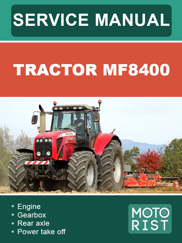
 MF8400 tractor, service e-manual
Автор: Motorist
Год издания: 0000
Content
Engine
Sisu engine - general
Introduction
Specifications and standards concerning fuel, oil and coolant
Main characteristics
Sisu tier 3 engine - general
Introduction
Specifications and standards concerning fuel, oil and coolant
Main specifications
Sisu tier 3 engine - removing and refitting
Checking the valve timing adjustment
Removing and refitting an injector
Removing and refitting the high pressure pump
Checking and adjusting the valve tip clearance
Description of the EEM
General - Dyna VT operation
General
Dyna VT transmission operating diagrams
Operation and use
DYNA VT hydraulics
Forward / Reverse high pressure relief valves
Scavenging valve
Control spool valve
DYNA VT hydraulic tests
Service tools
Replacing the DYNA VT unit
Desassembling the Dyna VT module
Assembling the Dyna VT module
Service tools
Final drive units
General
Removing a rear axle drive unit.
Refitting a rear axle drive unit
Disassembling a rear axle drive unit
Reassembling a rear axle drive unit
Service tools
Final drive units
General
Disassembling the rear axle brakes
Reassembling the rear axle brakes
Disassembling a wheel brake cylinder
Reassembling a wheel brake cylinder
Bleeding the brakes
Rear PTO
Assembling and disassembling the rear PTO
Disassembling the power take-off
Reassembling the power take-off
DANA final drive units
General
Removing and refitting the steering ram
Wheel alignment
Removing the final drive unit
Reassembling the final drive unit
Removing the swivel housing
Refitting the swivel housing
Service tools
DANA bearings and transmission shafts
General
Removing and refitting the transmission shafts and universal joints
Removing and refitting the front axle bearing supports
Replacing the friction rings
4-wheel drive clutch
General
Operation
Disassembling the 4WD clutch
Reassembling the 4WD clutch
Service tools
Universal joint shaft brake
General
Disassembling the universal joint shaft brake
Reassembling the universal joint shaft brake
Disassembling the universal joint shaft brake control
Reassembling the universal joint shaft brake control
Description of the circuit
General
Characteristics of the components
Illustrated diagram
Auxiliary hydraulics illustrated diagram
Hydraulic legends and diagrams
Legend of transmission hydraulics diagram
Legend of auxiliary hydraulics diagram
Transmission hydraulics diagram
Auxiliary hydraulics diagram
Layout of components
Main components of the hydraulic circuit
Layout of hydraulic circuit components
Trailer braking and ParkLock
General
Distribution block
Diagram of the trailer brake and ParkLock assembly
Braking valve and ParkLock
Priority valve
Trailer brake operation
ParkLock operation
Removing and refitting the distribution block and spool valve support
Removing and refitting the distribution block and braking block - ParkLock
Removing and refitting the ParkLock ram
Tractor Towing
Auxiliary spool valves
General
Layout of components and identification of ports
Spool valve operation
Diagram
Removing and refitting hydraulic couplers
Removing and refitting the auxiliary spool valves
Lift control valve
General
Layout of components and identification of ports
Removing - Refitting the distribution block
Diagram
Neutral position
Lifting position
Lowering position
Assembly procedure
Load Sensing hydrostatic steering
General
The Load Sensing principle
Orbitrol operation
Disassembling and reassembling the Orbitrol steering unit
Removing - refitting and disassembling - reassembling the steering ram
Steering column
Removing and refitting the steering column
Removing and refitting the control lever assembly
Removing and refitting the column tilt mechanism
Removing and refitting the column locking up mechanism
Disassembling the lower bush
Main braking circuit
General
Braking valve control
Relations between the different tractor braking circuits
Diagram
Rear brake cylinders
Removing the universal joint shaft brake
Bleeding the brakes
Disassembling and reassembling the pumps
General
Disassembling the steering pump and the variable displacement pump
Reassembling the steering pump and the variable displacement pump
Disassembling the service pump (18 bar)
Reassembling the service pump (18 bar)
Disassembling the lubricating pump
Reassembling the lubricating pump
Auxiliary hydraulics tests
General
Steering and cooling circuit
High flow rate auxiliary hydraulic circuit
Service tools
Fuse box
General
Fuse box for Europe
Fuse box - North America
Electrical diagrams
Cab equipment
Engine equipment
Bulb types
Lighting
Electronic units supply
EEM2 SisuDiesel - description
Presentation
Components on the engine
VP30 electronic injection pump (66ETA)
VP44 electronic injection pump (74ETA/84ETA)
Details of electronic components
Tractor / Engine Communication
Cab controls
SisuDiesel electronic injection - programming
Matching serial numbers
Location of softs for WinEEM
List of the various engine softs
SisuDiesel ELECTRONIC INJECTION - Tests and diagnostics
SisuDiesel Electronic injection - error codes
Reading error codes
List of error codes
EEM2 troubleshooting
EEM2 sensor diagnostics
EEM2 controller diagnostics
Fuel injection pump diagnostics
Electrical diagrams
Component characteristics
SisuDiesel electronic injection - electrical Diagrams
General
SisuDiesel engine harness
Electrical diagrams on the tractor
DCC2 - description
General
Description
Allocation of DCC2 pins
DCC2 (DynaVT) – Programming and setting parameters
Setting parameters
Programming
DCC2 (DynaVT) - Error codes
Reading error codes
List of error codes
Analysing error codes
DCC2 (DynaVT) - calibrations, constants and adjustments
Calibrating the ground speed (level 0)
Calibrating the throttle pedal potentiometer
Input at level 2 - CAL 2
Input at level 3 - CAL 3
Diagnostic mode
Adjusting the manoeuvring pedal
DCC2 (DynaVT) - Electrical diagrams
General
Electrical diagrams
GUF402 - Autotronic 4 - description
General
Allocation of autotronic 4 pins
GUF402 - autotronic 4 - Programming and setting parameters
Programming
Setting parameters
GUF402 - Autotronic 4 - tests and diagnostics
Safety function
Gearbox function
Front Axle function
Differential function
Power Take-Off function
GUF403 - autotronic 4 - error codes
Reading error codes
List of error codes
Analysing components and their error codes
Analysing other error codes
GUF404 - autotronic 4 - calibration
Input at level 1 - CAL 1
Hare / Tortoise range
Transmission
Coupler function
Power take-off
GUF405 - autotronic 4 - electrical diagrams
General
Electrical diagrams
Layout of components
11E10 - autotronic 5 ParkLock - description
General
Description of controls
ParkLock function activating conditions
ParkLock operation logic diagram
Allocation of Autotronic 5 ParkLock pins
GUF531 - autotronic 5 - ParkLock dynavt - programming and setting parameters
Programming
Saving to a file
Setting parameters
GUF532 - autotronic 5 - DynaVT ParkLock - tests and diagnostics
Diagnostics screen
GUF533 - autotronic 5 - DynaVT ParkLock - error codes
List of error codes
Analysing components and their error codes
GUF535 - autotronic 5 - ParkLock DynaVT - Electrical diagrams
General
Electrical diagrams
Layout of components
11F10 - autotronic 5 - linkage - description
General
Description
Console and armrest
Allocation of Autotronic 5 linkage calculator pins
GUF521 - autotronic 5 - linkage - programming and setting parameters
Programming
Saving to a file
Setting parameters
Table of constants
GUF522 - autotronic 5 - linkage - tests and diagnostics - MF6400/7400/8400
Autotronic 5 statuses
Electronic Linkage functions
GUF523 - autotronic 5 - linkage - error codes - MF6400/7400/8400
Reading error codes
List of error codes
Analysing components and their error codes
GUF524 - autotronic 5 - linkage - calibration and adjustments
Adjusting the position sensor
Calibrating the linkage
GUF525 - autotronic 5 - linkage - electrical diagrams - MF6400/7400/8400
General
Electrical diagrams
11G10 - Datatronic 3 - description
General
Architecture of the Datatronic 3 connections
Allocation of Datatronic 3 connectors
Description of controls
Using the Datatronic 3
GUF601 - Datatronic 3 - programming
Programming
Setting parameters
GUF604 - Datatronic 3 - Calibration and adjustments
General
Adjusting the sensor
Connecting to the tractor
Front Dual Control calibration
Rear Dual Control calibration
Trailed Implement Control (TIC) calibration
GUF605 - Datatronic 3 - Electrical diagrams
General
Electrical diagrams (8400)
Electrical diagrams (7400)
Electrical diagrams (6400)
GUF71 - SMS - JOYSTICK / FingerTIP - Setting parameters
Description
Setting parameters
GUF72 - SMS - JOYSTICK - Tests and diagnostics
Tests and diagnotics
GUF73 - SMS - JOYSTICK / FingerTIP - error codes
Operation and troubleshooting.
Reading error codes with EHRC linkage calculator
Reading error codes with Autotronic 5 linkage calculator
Display of error codes
Reading error codes stored by the electrohydraulic spool valves
List of error codes
GUF74 - SMS - JOYSTICK - settings
Joystick calibration
Adjusting EHS valve control levers
GUF75 - SMS - JOYSTICK / FingerTIP - electrical diagrams - auto 5 linkage
General
Electrical diagrams
11I10 - Autotronic 5 - suspended front axle - description
General
Operating mode
Regulation in suspension mode
Autotronic 5 connector
12C01 - Air conditioning - general
General
Block diagram
Technical characteristics
Safety instructions
General maintenance
Circuit troubleshooting
12C02 - Standard air conditioning
General
Electrical diagram
12C02 - 12C03 - Automatic air conditioning
Operating principle
Operation
Layout of components
Troubleshooting
Electrical diagram
GUF302 - Automatic air conditioning - tests and diagnostics
Operating statuses
Diagnostics screen
GUF303 - Automatic air conditioning - error codes
Reading error codes
List of error codes
GUF305 - automatic air conditioning - electrical diagrams
General
Connection to the tractor
Diagram
12C04 - air conditioning - refilling the unit
Draining the circuit and checking for leaks
Drafting the system and detecting leaks
Refilling the unit (engine stopped)
Checking pressures
Service tools
 Pontiac Fiero (1984-1988 гг.) Haynes Manual
Автор: Mike Stabblefield
Год издания:
Руководство Haynes по обслуживанию и ремонту автомобиля Pontiac Fiero (1984-1988 гг.).
 Daewoo Sens Service Manual
Автор: Николаенко Владимир Анатольевич
Год издания:
В данной книге на хорошем инженерном уровне, но в то же время просто и доступно, описаны модели ZAZ-DAEWOO SENS, с 2002 г. выпуска, торговое обозначение: T1311-01, T1311-02. Бензиновый двигатель с системой распределенного впрыска топлива:1. 3 л. - 51.
 Fiat Tipo and Tempra 1988-1996. Repair Manual – service guide
Автор: Коллектив авторов
Год издания:
Инструкция по ремонту и обслуживанию моделей Fiat Tipo и Tempra. Дано описание всех узлов и агрегатов и советы по их эксплуатации и техобслуживанию. Чертежи, таблицы и схемы электрооборудования.
Fiat Tipo - автомобиль итальянской компании Фиат. Был разработан дизайн студией IDEA. Выпускался с 1988 года по 1996 год.
 Tuning of manual transmission car, in eBook
Автор: Монолит
Год издания:
Content
Introduction
Transmissions / basic concepts
Internal components of a manual transmissionTroubleshooting and diagnostics
Overhaul gearbox
Transmissions Tremec / Borgwarner T-5
Transmission in the block with the main transfer Honda B-seriesModification of a mechanical transmission
Flywheel and clutch
