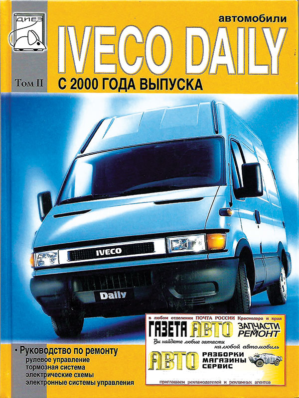
 Iveco Daily since 2000, service e-manual (in Russian), volume 2
Автор: Диез
Год издания: 0000
Content
Steering
General part
Power steering technical data
Special tools
Diagnostics
Power steering
TRW power steering
Power steering gear model ZF
Steering tips
Steering gear service
Power steering gear
Power steering pump
Elements of hydraulic and pneumatic circuits
Graphic symbols for hydraulic and pneumatic circuits, connections and assemblies
Valves
Receivers and batteries
Converters. Cylinders and calipers
Cylinders and calipers
Piping and their connections
General part
Flaring rigid pipes
Cutting rigid tubes
Braking system
Description
Braking system
Diagnostics
Technical data-hydraulic system
Technical data-brake system
Checks
The main components of the braking system
Bleeding the hydraulic circuit of the brake system
Bleeding the hydraulic circuits of the brake system using a bleeding kit
Proportional valve-regulator with mechanical control (models 35C - 40C - 45C - 50C - 60C - 65C)
Mechanically Operated Two-Circuit Proportional Control Valve (Models 29 L - 25 S)
Electro-hydraulic modulator assembly
Wheel sensor
Brake system repair
Front brakes
Caliper removal and installation
Rear brakes
Caliper removal and installation
Repair of brake calipers
Brake disc service
Grooving and grinding of brake discs
Parking brake repair
Parking brake adjustment
Cab air conditioning
General part
Ventilation
Heating and air conditioning system
Air conditioning
Heating
Automatic climate control
Main components
Control and safety devices
Air conditioner / heater unit "Marelli"
Air conditioning controls and deflector locations
Heater / air conditioner unit
Air conditioner / heater unit "Marelli"
Renovation work
Removal and installation of the air conditioner electronic control unit
Icing sensor
Electric fan
Heater radiator
Mixing actuator
Air intake actuator
Conditioned air sensor
Evaporator assembly
Expansion valve and evaporator tube
Compressor
Removing and installing compressor
Dust filter
Three-level contact pressure transducer and filter drier
Mechanical faults
Condenser
Heater "Marelli"
Electric fan
Heater control cables
Heater unit
Vehicle electrical equipment
Executive Summary
Component codes
General part
Ground points
Location of electrical components
Consumer nutrition
Ground points on the vehicle
Shielding and EMC concept
Ultrasonic welding of wires ("cold" welding)
Main electrical components of a car
Generator BOSCH KCBI 14 V 50-90 A
Generator BOSCH KCBI 14 V 70-120 A
Starter EV 12V 2,3 kW
Battery
Ignition switch
Power distributor
Remote general power switch (TGC)
Vehicle wiring
Injection system (3140 engines)
Engine wiring
Engine harness 8140.63 PC / NA (.9)
Engine harness 8140.43s ID / TCA (.11)
Welding locations for conductors 0140.63
Welding points of conductors 8140.43С
Engine harness 8140.43S UNIJET (.13)
Injection harness - V.G.T (.15)
F1A UNIJET engine harness (.10 -.12)
Wiring harness for injection system of engines F1A (.10 -.12) with and without EGR system
Chassis wiring
ABS wiring
Welding locations for conductors
Airbag system wiring with control unit. With one connector
Airbag system wiring with dual connector
Interior lighting wiring
Interior lighting wiring for minibuses (VAN 2/2 models)
Connector for lighting wiring harness to chassis wiring harness
Truck interior lighting wiring
Welding locations for conductors
Connectors between wiring harnesses
Delivery buses
General information
Diagnostic connector
Fuse and relay box
Indicator lights
Dashboard
Switch node
Steering column switch assembly
Cruise control system
Electric circuit diagrams (wiring diagrams)
Notes and technical data
Scheme 1A: starter
Scheme 1B: starter (.10 -.12)
Scheme 2A: preheating (.9)
Scheme 2B: preheating {.11)
Scheme 2C: preheating (.13 -.15)
Scheme 2D: preheating (.10 -.12)
Scheme 3: generator
Scheme 4: dashboard
Scheme 5: tachometer
Scheme 6A: tachometer (.9)
Scheme 6B: tachometer (.11)
Scheme 6C: tachometer (.10 -.12 -.13 -.15)
Scheme 7A: indicator lights (.9 -.11)
Scheme 7B; indicator lights (.10 -.12 -.13 -.15)
Scheme 8: exterior lighting (instruments in the cockpit)
Scheme 9A; outdoor lighting (side lights)
Scheme 9B: outdoor lighting (side lights, bus)
Scheme 10: low and high beam headlights
Scheme 11A: fog lamps and headlights
Scheme 11B: fog lamps and headlights (bus)
Scheme 12: front light control
Scheme 13A: emergency lighting and direction indicators
Scheme 13B: emergency lights and direction indicators (bus)
Scheme 14A: brake lights
Scheme 14B: stop lights (bus)
Scheme 15A: reversing lights
Scheme 15V: reversing lights (bus)
Scheme 16: klaxon
Scheme 17: windshield and headlight washer
Scheme 18a: Heated windshield
Scheme 18v: windshield heater (.10 -.12)
Scheme 19: radio equipment
Scheme 20A: interior lighting and cigarette lighter
Scheme 20B: interior lighting (bus)
Scheme 20C: interior lighting for 6 + 1 models
Scheme 20D: interior lighting and cigarette lighter (F1A)
Scheme 21A: immobilizer (.9)
Circuit 21V; immobilizer (.11)
Scheme 21C: immobilizer (.10 -.12 -.13 -.15)
Scheme 22A: diagnostic connector (.9-.11)
22B Scheme: diagnostic connector {.10-.12-.13-.15)
Scheme 23A: engine cooling system (.9)
Scheme 23B: engine cooling system (.11)
Scheme 23C: engine cooling system (.13 -.15)
Scheme 23D: engine cooling system (.10-.12)
Scheme 24A: electronic EGR (.9)
Scheme 24B: electronically controlled EGR system from the edc unit (.13)
Scheme 24C: electronically controlled EGR system from EDC unit (.10 -.12)
Scheme 25A: preheater timer (.9)
Scheme 25B: preheater timer {.11)
Scheme 26A: diesel Control Unit {EOC) (. 13)
Scheme 26B: diesel engine control (EDC) and variable geometry turbine (.15)
Scheme 26C: diesel control unit (EDC) and turbine with wastegate (.13)
Scheme 26D: diesel control unit (edc) without EGR system (.10 -.12)
Scheme 27A: fuel filter heating (.9 -.11) / ОРТ 2287
Scheme 27B: fuel filter heating (.13 -.15)
Scheme 27C: fuel filter heating (.10 -.12)
Scheme 28A: passenger door electric window / ort 693
Scheme 28B: power window driver's door / ort 4028
Scheme 28C: Power windows for driver and passenger doors (.10-.12)
Scheme 29: heated rear-view mirrors / ORT 697
Scheme 30: electric drive of rear-view mirrors / ORT 2714
Scheme 31: heated windshield / ORT 605
Scheme 32: heated rear window / ort 6815
Scheme 33: abs / ebd / abd / ort 2091 systems
Scheme 34A: air suspension control system without air receiver (.9-.10-.11 -.12-.13)
Scheme 34B: air suspension control system with air receiver (.9 -.10 -.11 -.12 -.13)
Scheme 34C: VB TECHNIEK air suspension control system (.9 -.10 -.11 -.13-.15)
Scheme 35A: automatic climate control (.9) / ОРТ 6650
Scheme 35V: automatic climate control (.11) / ORT 6650
Scheme 35C: automatic climate control (.13 -.15) / ORT 6650
Scheme 35D: automatic climate control (.9 -.10 -.11 -.12 -.13 -.15) / ORT 6650
Scheme 35E: automatic climate control (.10 -.12) / ОРТ 6650
Scheme 36: electronic tachograph / ORT 5130-5131
Scheme 37A: airbag and pretensioners / ORT 4495 - 4496
Scheme 37B: airbag and pretensioners / ORT
Scheme 38: door lock with anti-theft protection / ORT 6890
Scheme 39A: front differential lock / ORT 131
Scheme 39B: rear differential lock / ORT 131
Scheme 40: 13-pole power connector / OPT 6520
Scheme 41A: PTO connection block (.9 -.11)
Scheme 41B: PTO connection block (.10 -.12 -.13 -.15)
Scheme 42A: heated driver's seat (bus) / ORT 6628
Scheme 42V: heated seats / ORT 6644
Scheme 43: daytime lighting models for the european market / ORT 2536
Scheme 44: door lock / ORT 6536
Scheme 45A: retarder model TELMA SCUDATI (.9 -.11) / ОРТ 235
Scheme 45B: retarder model TELMA (.10 -.12 -.13 -.15) / ORT 235
Scheme 46: remote general power switch / ОРТ 2532
Scheme 47: cruise control system / ORT 2463
Scheme 48: engine cooling jacket heater / ОРТ 6654
Scheme 49: electric sliding door / ORT 9/12
Scheme 50: tilt-and-slide door / ORT 9/ 12
Scheme 51: electrical equipment of the awning / ORT 640
Scheme 52: central emergency management / ORT 2546
Scheme 53: electrical models for the north african market
Scheme 54: two-tone horn (bus)
Scheme 55: tilt and slide door RHD models
Electronic systems
Immobilizer
System components
ABS / EBD / ABD systems
Four-scheme diagonal braking system
Four-scheme parallel split braking system
Exhaust gas circulation system (8140.63)
COMMON RAIL system (8140 / 35S engines)
COMMON RAIL system (F1A engines)
Hydraulic system (COMMON RAIL - F1А engines)
Diesel control unit EDCMS 6.3
System operation
Electronic diesel control unit (EDC) MS 6.3
Fault codes (flashing codes)
Climate control
System components
Built-in system diagnostics
Airbags
System components
System diagnostics
Electronic tachograph
Security device with door blocking
System operation
Main components of the system
EGAS pneumatic suspension
Location of components on the car
System components
How it works
Air suspension with electronic control VB TECHNIEK
System components
System operation
Diagnostics
Tilt-and-slide door
System components
How it works
Electric retarder TELMA
VGT variable geometry turbocharger
Wheels and tires
Description
Tire pressure
Diagnostics
Static wheel balancing
The dependence of the behavior of the tire on the pressure in it
 Pontiac Fiero (1984-1988 гг.) Haynes Manual
Автор: Mike Stabblefield
Год издания:
Руководство Haynes по обслуживанию и ремонту автомобиля Pontiac Fiero (1984-1988 гг.).
 Daewoo Sens Service Manual
Автор: Николаенко Владимир Анатольевич
Год издания:
В данной книге на хорошем инженерном уровне, но в то же время просто и доступно, описаны модели ZAZ-DAEWOO SENS, с 2002 г. выпуска, торговое обозначение: T1311-01, T1311-02. Бензиновый двигатель с системой распределенного впрыска топлива:1. 3 л. - 51.
 Translation Techniques. English - Russian. Практические основы перевода
Автор: Т. А. Казакова
Год издания:
Учебное пособие предназначается изучающим английский язык и входит в систему предметов, обучающих теории и практике перевода. Материал пособия направлен на освоение и развитие практических навыков перевода с английского языка на русский и наоборот.Основным принципом построения пособия, отбора и расположения учебного материала является создание систематического представления о способах, средствах и приемах преобразования языковых единиц в процессе двустороннего перевода. Пособие может бытьиспользовано в рамках учебного процесса на факультетах иностранных языков, для обучения переводчиков, а также для самостоятельных занятий студентов, аспирантов, преподавателей английского языка и начинающих переводчиков.
 Fiat Tipo and Tempra 1988-1996. Repair Manual – service guide
Автор: Коллектив авторов
Год издания:
Инструкция по ремонту и обслуживанию моделей Fiat Tipo и Tempra. Дано описание всех узлов и агрегатов и советы по их эксплуатации и техобслуживанию. Чертежи, таблицы и схемы электрооборудования.
Fiat Tipo - автомобиль итальянской компании Фиат. Был разработан дизайн студией IDEA. Выпускался с 1988 года по 1996 год.
 Italiano in cinque minuti. Volume 1.
Автор: Galasso Sabrina, Trama Giuliana
Год издания:
Грамматические и лексические упражнения по итальянскому языку.