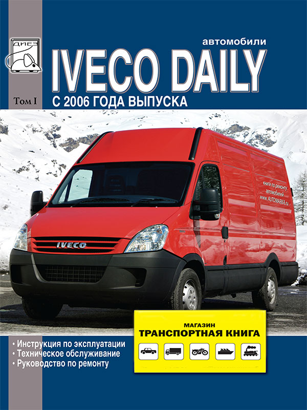
 Iveco Daily since 2006,, service e-manual (in Russian), volume 1
Автор: Диез
Год издания: 0000
Contents
Operating instructions
Electronically controlled air suspension ECAS
Pneumatic suspension (can only be installed on 35C / 65C models)
Starting the engine and moving the car
Immobilizer
Car keys
Code card
Emergency start engine ignition switch position
Enabling the immobilizer
Disabling the immobilizer
Starting the engine
Engine shutdown
Centralized door locking system (if installed)
Cold weather starting
Self-diagnosis of car systems
Centralized door locking system with electronic alarm (if installed)
AGILE gearbox (if fitted)
Display vehicle operation with automatic transmission
Speed ??programming
Using the power take-off (if equipped)
Fault signaling
Starting the engine by towing the vehicle
Engaging the rear axle differential lock
Anti-lock braking system (ABSJ / pressure limiting valve (EBD) / tire adhesion monitor (ABD)
ESP8 - electronic stability control system
Grade hold system
ABS8 (if installed)
Cruise control (if installed)
Power take-off (if included in the transmission)
Works performed by the driver independently
Precautions when working with electronic control units installed in the vehicle
Mandatory instructions
Car towing
Driver checks
Before every trip
Scheduled maintenance
Specifications
Engine
Maintenance
Car maintenance schedule
Inspection and maintenance checklist
Maintenance operations
M1 maintenance
Maintenance M2
Maintenance EP1
Maintenance EP2
EPZ maintenance
Maintenance T1 (at the beginning of each spring)
Maintenance T2 (at the beginning of each winter)
Technical maintenance of technical specifications
Maintenance T4
Under-dash fuse and relay box
Under-dash fuse and relay box (EURO 4, EURO 5, NATURAJ POWER)
Fuse and relay box in the engine compartment (EURO 4, EURO 5. NATURAL POWER)
Fuse and relay box in the engine compartment (EURO 4) (EURO 4, EURO 5, NATURAL POWER) outdoor unit
Engine compartment fuse and relay box (EURO 5)
Additional fuse box (engine compartment)
Additional fuse box in the engine compartment (EURO 5)
Engine compartment fuse and relay box (NATURAL POWER)
Additional fuse box in the engine compartment (NATURAL POWER)
Menu control panel
Display message
BASE version display
BASE version menu structure - engine start (ignition switch ON)
Dashboard COMFORT version
COMFORT version display
Diesel particulate filter (particulate filter for diesel engines)
F1A engine
Engine removal / installation
Replacing the timing belt
Replacing electrically operated fuel injectors
Exhaust toxicity, smoke and noise
F1AE0 engine
Diagnostics
Basic operations with an engine not removed from the vehicle
Tightening torques for threaded connections
Longitudinal section of the engine with horn system
Cross section of an engine with horn system
Repair of the F1A engine
Dismantling the engine at the stand
Renovation work
Cylinder block
Crankshaft
Engine assembly
Installing the rear oil seal
Flywheel
Assembly of pistons with connecting rods
Pistons
Rods
Cylinder head
Valves
Valve guides
Valve seats
Valve springs
Swing levers (rockers) - pushers
Installing the cylinder head
Gas distribution system
Camshaft
Adjusting the tension of the air conditioning compressor drive belt
Camshaft position sensor
Crankshaft speed sensor
Lubrication system
Oil and vacuum pump assembly (GPOD)
Oil pressure reducing valve
Oil filter
Heat exchanger modine
Crankcase ventilation and oil separator
Cooling system
Fan clutch
Water pump
Thermostat
Turbocharging
Turbocharger
Repair
Pressure reducing valve
Exhaust gas recirculation
Power system
Electronically controlled high pressure fuel injection (MS 6.3)
System operation
Hydraulic part of the fuel system
Fuel pump
Fuel lines
High pressure fuel pump
High pressure fuel pump device
Pressure regulator valve
Mechanical booster pump
Hydraulic accumulator (RAMP)
Pressure reducing valve
Electrically operated injectors
Electrical / electronic components
Electronic control unit edc 16 for EUR04 engines
Sensors
Actuators
Regulators with pulse width modulation (PWM)
Differences of EURO4 motors
Exhaust Gas Recirculation (EGR)
Control solenoid valve
Mass air flow sensor (DMRV)
Throttle assembly (body)
EGR heat exchanger
Exhaust gas cleaning system (particulate filter)
Particulate filter regeneration system
Muffler with catalytic particulate filter
Fuel system
F1C engine
While the engine has not yet been removed from the vehicle
Electrically operated injectors
High pressure fuel pump SRZ
High pressure fuel pipes
Fuel rail components
Removal and engine installation
Withdrawal
Installation
Checks
Removing air from the mains (pumping)
Replacing the A / C compressor drive belt (tensioner option)
Replacing the power steering belt and generator
Replacing the water pump
Replacing the high pressure fuel pump (injection pump)
Replacing the power steering pump
Replacing the front crankshaft oil seal and front engine cover gasket
Replacing the vacuum and oil pump assembly
Replacing the rear crankshaft oil seal
Replacing fuel injectors
Removing / installing cylinder head
General view of the engine
Sticker
Cylinder block marking
Characteristic curves
Technical data
Special tools
Tightening torques of threaded connections, НМ
F1C engine repair
Dismantling the engine at the workbench
Repair
Cylinder block
Table of measurements of the diameters of the main and connecting rod journals
Crankshaft 188 Checking the crankshaft
First main journal (timing side)
Root necks No. 2, No. 4
Root collar No. 3
Rear neck (flywheel side)
Connecting rod journals
Installing the engine
Flywheel
Pistons with connecting rods
Pistons
540830 connecting rods
Bushings
Dismantling the cylinder head
Valves
Valve guides
Valve seats
Valve springs
Rockers and hydraulic supports
Cylinder head assembly
Gas distribution mechanism drive
Crankshaft locking
Gas distribution mechanism drive
Lubrication system
General information
Oil system operation
Oil / Vacuum pump assembly
Oil filter
Heat exchanger
Crankcase ventilation system
Cooling system
Description
Electromagnetic clutch
Water pump
Thermostat
Turbocharging
Repair
Bypass valve
Turbocharger GARRET GT 2256 TC variable turbine geometry (F1C E0481 V engine - 166 hp)
Repair
Fuel system
Electronically controlled high pressure battery power system (EDC 16)
General information
System operation
Fuel system operation
Fine fuel filter
Booster fuel pump
Fuel filter
High pressure fuel pump (TNVD)
Pressure regulator
Mechanical booster pump
Electro-controlled (electromechanical) fuel injectors
Electrical and electronic components
Electronic control unit (ECM) EDC 16
Electronic control unit for glow plug power supply
Glow plugs
Sensors
Actuators (executive devices)
F1С EURO-4 engines
Specifications
Exhaust gas recirculation (EGR) heat exchanger removal / installation
Exhaust system
Removing the muffler
Removing the catalyst and filter
Installation
Clutch
Description
Diagnostics
Technical data
Removing and installing clutch
Removing and installing release bearing
Clutch actuator
Hydraulic clutch actuator
Removing-installing pedal board
Pedal board
Clutch with automatic wear compensation - complete with gearbox 6 AS'300 VD
Removing and installing clutch with automatic wear compensation
Gearbox
Diagnostics
Removal-installation of the checkpoint
Gearbox control
Gearbox 5 S 300
Mechanism of selection and inclusion of gears
Safety devices
Technical data (specifications)
5 S 300 gearbox repair
Gearbox
Disassembly of the main shaft
Input shaft
Disassembly of the transfer (intermediate) shaft
Checks
Main shaft assembly
Stems - forks - selector - carrier
Gearbox assembly
Gearbox 6 S 400 O.D
Technical data (specifications)
Tightening torques
6 S 400 gearbox repair
Gearbox
Disassembly of the gearbox
Removing the bearings from the rear cover
Removing bearings from gearbox housing
Disassembly of the main shaft
Disassembly of the gearbox input shaft
Dismantling the intermediate shaft
Synchronizers
Installing the intermediate (transfer) shaft
Main shaft assembly
Stems - forks - selector - carrier
Gearbox assembly
Automatic transmission 6 S 400 A O.D
Main functions of the system
Vehicle restraint system on a slope
Management system structure
Technical data
Tightening torques for threaded connections
Diagnostics
MODUS connection - IT 2000 - E.A.SY
Removal and installation of the checkpoint
Gearbox repair
Body-gearbox wiring harness
Gearbox cable harness
Calibration
Power take-off
Technical data
Assembly instructions
Electric actuator for power take-off
Cardan shafts
Technical data
4x2 models
4x2 models
Removing and installing propeller shaft
Rear axle
Troubleshooting
Rear axle NDA RS
Removing / installing rear axle
Description
Technical data
Rear axle NDA RG
Removing / installing rear axle
Description
Technical data
Rear axle 450511
Rear axle technical data 450511
Removing / installing rear axle
Description
Technical data
Rear axle repair
Build
Wheel hub repair
Differential repair operations
Front axle
Diagnostics
5817 front axle
Description
Technical data
Removing and installing front axle
5817 front axle repair
Removing and installing a wheel hub
Removing / installing steering knuckle
5818 front axle
Description
Technical data
5818 Front axle repair
Replacing the driving wheel of the ABS sensor
Installation
Removing and installing a wheel hub
5819 front axle
Description
Front suspension 5819
Technical data
5819 front suspension repair
5823 Front axle
Description
Technical data
Removal and installation of bridge 5823
Repair of the front suspension 5823
Removing and installing a wheel hub
Replacing the driving wheel of the ABS sensor
Installation
Replacing the wheel stud
Camber and toe
Description
Camber angle
Angle of lateral inclination of the axle of rotation of wheels
Caster angle of the wheel axis
Wheel alignment
Wheel alignment angles
Checking wheel alignment
Mechanical suspension
Mechanical front suspension
Description
Cross leaf spring (models 29 L - 35 S - 35 С)
Specifications
Front single leaf spring
Anti-roll bar
Front shock absorbers
Tools
Tightening torques for threaded connections (NM)
Renovation work
Suspension repair
Suspension arms
Replacing the suspension arm bushings
Anti-roll bar model 29 L - 35 S
Front shocks 29 L - 35 S
Leaf spring suspension
Torsion bar suspension (front axles 5819 model 35 С - 40 С - 45 С - 50 С)
Repair of jet suspension rods
Replacing the swivel tips
Torsion bars
Replacing silent blocks and bumpers
Replacing the swivel tips
Adjusting the pre-tension bar
Front anti-roll bar 35 C - 40 C - 45 C - 50 C
Front shock absorbers 35 C - 40 C - 45 C - 50 C
Suspension repair
Replacing the swivel tips
Torsion bars
Replacing rubber grommets
Rear suspension
Technical data
Tools
Tightening torques for threaded connections (NM)
Rear springs
Renovation work
Spring assembly
Replacing bushings
Rear shock absorbers
Rear anti-roll bar
Pneumatic suspension
Diagnostics
Rear air suspension - VB-TECHNIEK model flashing code
Rear air suspension - WABCO model
Flashing code
General part
WABCO air suspension (for models 29 L - 35 S)
Technical data
WABCO Pneumatic System (ECAS)
Electronic control
How the air suspension works
Models without ABS
ABS models
Automatic chassis trim, raise and lower
Main components of the system
Air supply unit
Electronic control unit
Clearance sensor
Pneumatic element (air spring)
Load sensing valve
Rear suspension repair
Leaf spring
Rear shock absorbers
Rear anti-roll bar
Panhard's jet thrust
 Pontiac Fiero (1984-1988 гг.) Haynes Manual
Автор: Mike Stabblefield
Год издания:
Руководство Haynes по обслуживанию и ремонту автомобиля Pontiac Fiero (1984-1988 гг.).
 Daewoo Sens Service Manual
Автор: Николаенко Владимир Анатольевич
Год издания:
В данной книге на хорошем инженерном уровне, но в то же время просто и доступно, описаны модели ZAZ-DAEWOO SENS, с 2002 г. выпуска, торговое обозначение: T1311-01, T1311-02. Бензиновый двигатель с системой распределенного впрыска топлива:1. 3 л. - 51.
 Translation Techniques. English - Russian. Практические основы перевода
Автор: Т. А. Казакова
Год издания:
Учебное пособие предназначается изучающим английский язык и входит в систему предметов, обучающих теории и практике перевода. Материал пособия направлен на освоение и развитие практических навыков перевода с английского языка на русский и наоборот.Основным принципом построения пособия, отбора и расположения учебного материала является создание систематического представления о способах, средствах и приемах преобразования языковых единиц в процессе двустороннего перевода. Пособие может бытьиспользовано в рамках учебного процесса на факультетах иностранных языков, для обучения переводчиков, а также для самостоятельных занятий студентов, аспирантов, преподавателей английского языка и начинающих переводчиков.
 Fiat Tipo and Tempra 1988-1996. Repair Manual – service guide
Автор: Коллектив авторов
Год издания:
Инструкция по ремонту и обслуживанию моделей Fiat Tipo и Tempra. Дано описание всех узлов и агрегатов и советы по их эксплуатации и техобслуживанию. Чертежи, таблицы и схемы электрооборудования.
Fiat Tipo - автомобиль итальянской компании Фиат. Был разработан дизайн студией IDEA. Выпускался с 1988 года по 1996 год.
 Italiano in cinque minuti. Volume 1.
Автор: Galasso Sabrina, Trama Giuliana
Год издания:
Грамматические и лексические упражнения по итальянскому языку.