 Bulldozers Komatsu D275A, user e-manual
Автор: Motorist
Год издания: 0000
Content
General Information
Design, operation and maintenance standards
Power transmission
General view of the power transmission
Damper and universal joint
Torque converter, power take-off
Torque converter, PTO (lockup clutch)
Torque converter (lockup clutch)
Torque converter valve
Torque converter valve (with lock-up clutch)
Extraction pump
Transmission controls
Gearbox
Transmission ECMV valve
Head unloader valve and torque converter valve
Power train pump, steering gear lube pump
Grease relief valve
Steering, brake control
Bevel gear shaft, steering clutch and brake
Steering control valve
Steering clutch ECMV valve
Steering Brake ECMV
Parking brake valve
Brake safety valve
Optional power train relief valves for cold start
Final drive
Asterisk
Crawler frame
Tension spring
Guide wheel
Support roller
Carrier roller
Track roller trolley
Track chain
Main frame
Pendant
Working hydraulic system diagram equipped
Piping diagram PPC control holster
Work equipment controls
Implement pump
Radiator fan pump
Radiator fan motor
Hydraulic tank
Hydraulic accumulator
ppc lockout valve
PPC valve
Piston valve
Quick release valve
Finger puller switch
Electro-machine finger puller valve
Diverter valve
Control valve operation
Cylinder support
Dump
Ripper equipment
Cabin mount
Cab
Conditioner
Engine controls
Engine retarder
Control system
Control panel
Sensors
Electrical equipment
Joystick control system
Preheater system
Points to remember when troubleshooting
How to use the troubleshooting tables
Engine starts with difficulty (starting always takes time)
Engine won't start
Engine won't crank
Engine cranks but no exhaust gases come out (no fuel injection)
Exhaust gases come out, but the engine does not start (fuel injection is present)
Engine revs unevenly (poor revs)
Engine stops during operation
Engine runs uneven
Exhaust gases are black
Excessive oil consumption (or exhaust gases are blue)
Oil gets dirty quickly
Excessive fuel consumption
Oil in the coolant or splashing or low Coolant level
The oil pressure warning light comes on
The oil level is rising
The coolant temperature becomes excessively high (overheating)
Extraneous noise is heard
Excessive vibration
How to use the troubleshooting tables
Engine starts with difficulty (starting always takes time)
Checking and adjusting
Regulatory tables
Table of standard values ??for the engine
Chassis guideline table
Checking and adjusting
Troubleshooting
Disassembly and assembly
How to use this manual
Work Precautions
Removing the starter assembly
Installing the starter assembly
Removing the generator assembly
Installing the complete generator
Removing the inner element of the engine oil cooler assembly
Installing the engine oil cooler inner assembly
Removing the high pressure fuel pump assembly
Installation high pressure fuel pump assembly
Special tool drawing
Removing the water pump assembly
Installing the water pump assembly
Removing the nozzle holder assembly
Installing the nozzle holder assembly
Removing the turbocharger assembly
Installing the turbocharger assembly
Removing the front engine seal
Installing the engine front oil seal
Removing the rear engine seal
Installing the engine rear oil seal
Removing the cylinder head assembly
Installing the cylinder head assembly
Removing the thermostat assembly
Installing the thermostat assembly
Removal and installation of the fuel tank assembly
Removing and installing the main radiator assembly
Removing and installing the optional heatsink assembly
Removing and installing hydraulic oil cooler assembly
Removing and installing a radiator assembly
Removing and installing the engine
Removing and installing damper assembly
Disassembly and assembly of the damper assembly
Removing and installing power train assembly
Disconnecting and Connecting the Power Train Assembly
Disassembly and assembly of the power take-off assembly
Disassembly and assembly of the torque converter assembly
Disassembly and assembly of the gearbox assembly
Disassembly and assembly of the steering gear housing assembly
Removing and installing the suction pump
Removing and installing implement pump assembly
Removing and installing blower pump assembly
Removing and installing the power train and steering oil pump assembly
Removing and installing final drive assembly
Disassembly and assembly of the final drive assembly
Removing and installing track frame assembly
Removal and installation of the guide wheel assembly
Disassembly and assembly of the guide wheel assembly
Removing and installing tension spring assembly
Disassembly and assembly of the tension spring assembly
Removing and installing the track roller assembly
Disassembly and assembly of the track roller assembly
Removing and installing carrier roller assembly
Disassembly and assembly of the support roller assembly
Removal and installation of the 1st cart assembly
Removal and installation of the 2nd, 3rd and 4th cart assembly
Disassembly and assembly of the cart assembly
Uncoupling and installing track assembly
Field Assembly and Disassembly of the track assembly
Removing and installing kingpin assembly
Removal and installation of the balance beam assembly
Disassembly and assembly of the balance beam bushing
Removing and installing implement control valve assembly
Dismantling and assembly of the hydraulic cylinder assembly
Blade assembly removal and installation
Ripper assembly disassembly and assembly
Removing and installing operator cab assembly
Removing and installing floor frame assembly
Removal and installation of the transmission controller assembly
Removal and installation of the steering controller assembly
Removal and installation of the engine hood assembly
Removing and installing fan drive assembly
Removing and installing fan motor
Removing the fire heater
Installing the fired heater assembly
Other
Power transmission hydraulic schematic
Working equipment hydraulic schematic
Circuit diagram
Cabin wiring diagram
Diagram of electrical equipment of the air conditioner
 Pontiac Fiero (1984-1988 гг.) Haynes Manual
Автор: Mike Stabblefield
Год издания:
Руководство Haynes по обслуживанию и ремонту автомобиля Pontiac Fiero (1984-1988 гг.).
 Daewoo Sens Service Manual
Автор: Николаенко Владимир Анатольевич
Год издания:
В данной книге на хорошем инженерном уровне, но в то же время просто и доступно, описаны модели ZAZ-DAEWOO SENS, с 2002 г. выпуска, торговое обозначение: T1311-01, T1311-02. Бензиновый двигатель с системой распределенного впрыска топлива:1. 3 л. - 51.
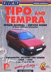
 Fiat Tipo and Tempra 1988-1996. Repair Manual – service guide
Автор: Коллектив авторов
Год издания:
Инструкция по ремонту и обслуживанию моделей Fiat Tipo и Tempra. Дано описание всех узлов и агрегатов и советы по их эксплуатации и техобслуживанию. Чертежи, таблицы и схемы электрооборудования.
Fiat Tipo - автомобиль итальянской компании Фиат. Был разработан дизайн студией IDEA. Выпускался с 1988 года по 1996 год.
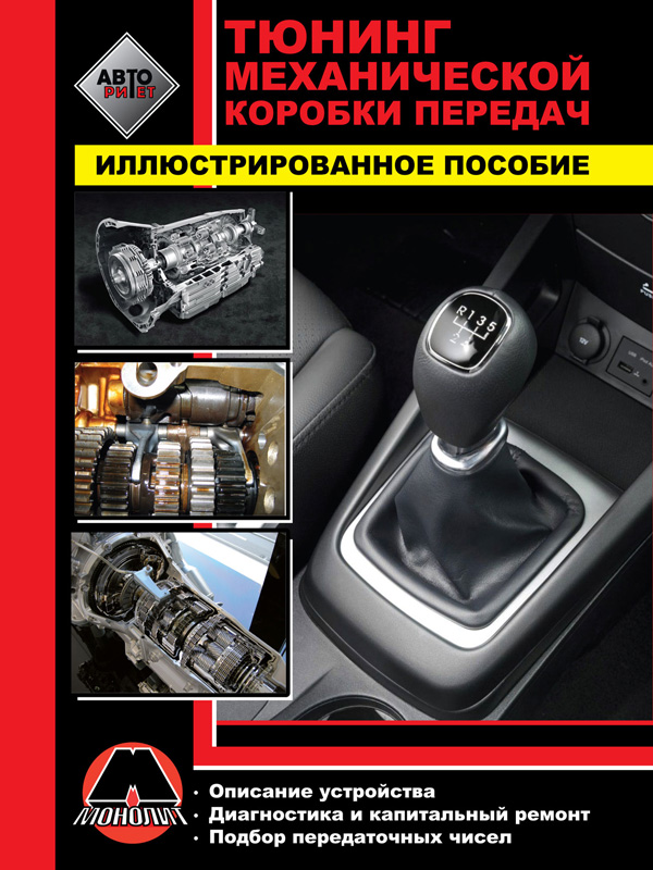
 Tuning of manual transmission car, in eBook
Автор: Монолит
Год издания:
Content
Introduction
Transmissions / basic concepts
Internal components of a manual transmission
Troubleshooting and diagnostics
Overhaul gearbox
Transmissions Tremec / Borgwarner T-5
Transmission in the block with the main transfer Honda B-series
Modification of a mechanical transmission
Flywheel and clutch
 Anatomy of bone system. The manual for medical students / Анатомия костной системы. Учебное пособие для медицинских вузов
Автор: Г. И. Ничипорук
Год издания:
Данное пособие является английской версией учебника профессора И. В. Гайворонского «Нормальная анатомия человека», который был издан в России 9 раз и одобрен Министерством образования Российской Федерации.
Структура пособия соответствует современным стандартам медицинского образования в России и важнейшим Европейским стандартам. Английская и латинская терминология приведены в соответствии с Международной анатомической номенклатурой.
 Anatomy of bone system. The manual for medical students / Анатомия костной системы. Учебное пособие для медицинских вузов
 Anatomy of bone system. The manual for medical students / Анатомия костной системы. Учебное пособие для медицинских вузов