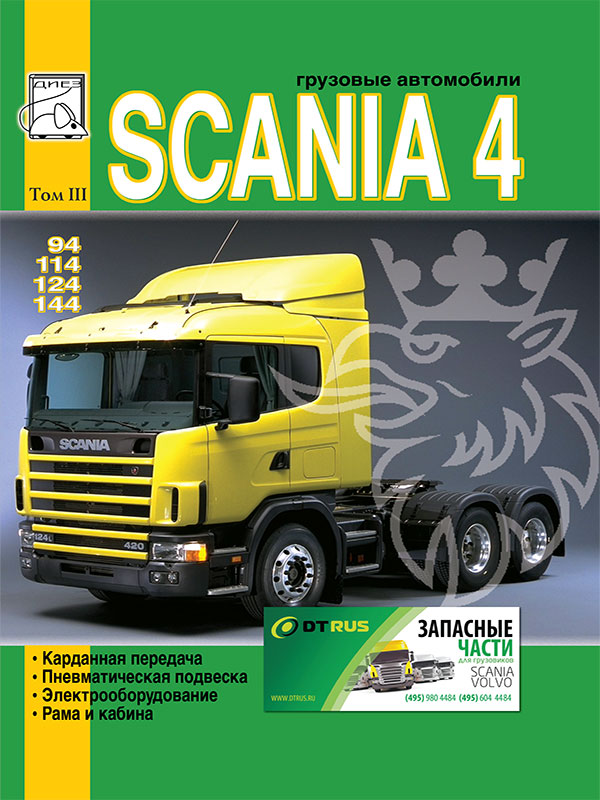
 Scania 94 / 114 / 124 / 144 with engines of 9 / 11 / 12 / 14 liters, service e-manual (in Russian), volume 3
Автор: Диез
Год издания: 0000
Volume 3 provides repair information:
- cardan transmission
- air suspension;
- electrical equipment;
- frames and cabins.
Content
Cardan shafts
Main propeller shaft
Removing shafts P300 - P520
Removing the shaft P600
Disassembly of shafts P300 - P600
Assembly of shafts P300 - P600
Installation of shafts P300 - P500
P600 shaft installation
Installation of shafts P420 and P520
Intermediate propeller shaft
Withdrawal
Disassembly
Suspended bearing
Cross gimbal
Shaft disassembly P300 - P400
Shaft disassembly P500 - P600
Assembly, all types of cross joints
Checking the main and intermediate propeller shafts
Shortening friction welded universal joint shafts
Shortening of cardan shafts P300, P400, P500 and P600
Shortening of intermediate cardan shafts P310, P410, P510 and P610
Runout measurement
Air Suspension - mechanical components
Suspension parts drive / driven axle, except driven axle 6x2 / 4
Tightening ladders
Suspension parts driven axle 6X2 / 4
Tightening ladders
Front axle pneumatic elements
Pneumatic elements of the driving / driven axles, except for the driven axle 6X2 / 4
Replacing pneumatic elements, drive / driven axle
Replacing the lifting pneumatic elements of the driven axle
Replacement of pneumatic elements of the driven axle 6X2 / 4
Replacing the lifting pneumatic elements of the driven axle
Longitudinal jet thrust
Length of jet rods
Withdrawal
Replacing bushings
Checking the caster angle of the axis of rotation (caster)
Caster Caster
Transverse jet thrust
Anti-roll bar
Fastening air cushions
Front axle
Leaf spring suspension of the VT300 rear axle
Spring
Spring bracket
Service, lubrication
Spring bracket oil seals
Wear ring
Bearing sleeves
Reactive thrust
Wheel alignment
Replacement of jet thrust, axles AD 1300 and AD 1500
Replacement of jet thrust, axle AD1100
Anti-roll bar
Shock absorbers
Suspension damping cable stops
Height of pneumatic elements
Chassis height
Front axle
Rear axle
Mechanical air suspension control
Suspension height control valve
Automatic maintenance of a given height level
Maintaining the suspension level
Manual suspension level control
Electronic air suspension control (ELC)
System description
Control unit
Configuration
Replacing the control unit
Calibration
Incoming signals
Height level sensors
Pressure tracking, rear axle (6X2)
System operation
M1 and M2 levels programming
Control panel pressure gauge
Valve for chassis 4X2A
Valves for 4X2B chassis
Suspension wiring diagram 4x2, 6x2 with ELC system
Valve for chassis 6X2B
Wheel arrangement 6X2 with additional air receivers
Warning lamps system malfunctions
Troubleshooting
System malfunctions
Diagnostic capabilities
ELC fault codes on 4 * 2A / B trucks
ELC fault codes on 6 * 2 B trucks
Electronic air suspension control second generation (ELC 2)
System description
Position of bridges in motion
Trim control modes
Controls operation
Axle position switch
Cars with two driven axles
Vehicles with tandem axles
Load sharing mode
Configuration
System electrical equipment
Control unit
Warning lights
Valves and gauges
Solenoid valve block
Solenoid valve V32
Height level sensors Т72 and Т73
Pressure sensor T70 and T71
Valve inputs and outputs V54 + V55
Second generation ELC fault codes
Second generation ELC pneumatic and electrical suspension circuits
Pneumatic system
Pneumatic suspension scheme for 4X2A wheel arrangement
Pneumatic suspension scheme for 4X2B wheel arrangement
Pneumatic suspension scheme for wheel arrangement 6X2A, 8X2A, 6X2 * 4A and 8X2 * 6A
Pneumatic suspension scheme for wheel arrangement 6X2B and 6X2 * 4B
Pneumatic suspension scheme for 6X4A and 8X4A wheel arrangement without load transfer function
Skeleton diagram for 6X4A and 8X4AC wheel arrangement with load redistribution function
Pneumatic suspension scheme for 6X4B wheel arrangement without load transfer function
Pneumatic suspension scheme for 6X4B wheel arrangement with load redistribution function
Pneumatic suspension scheme for wheel arrangement 6X2 / 4A
Pneumatic suspension scheme for 6X2 / 4V wheel arrangement
Pneumatic suspension scheme for wheel arrangement 8X2B and 8X2 * 6B
Pneumatic suspension scheme for wheel arrangement 8X2 / 4A
Pneumatic suspension scheme for wheel arrangement 8X2 / 4B
Pneumatic suspension scheme for 8X4V wheel arrangement without load transfer function
Air suspension wiring diagrams
Pneumatic suspension scheme for wheel arrangement 8X4B with load redistribution function
Electrical diagrams
Cab suspension
Cab tilt cylinder
Cab tilt stop
Front pneumatic support
Rear pneumatic support
Anti-roll bar
End delimiter replacement
Chassis frame
Frame construction
Spars
Crossbars
Front frame
Central part
Back
Type notation
Frame forces and kinematics
Static loads
Dynamic loads
Shear Loads
Torsional loads
Load distribution to frame components
Working with frames made of wear-resistant steel
Straightening
Chassis modifications
Welding
Electric welding
Removing cross members
Hole welding
New holes
Installation of crossbars
Eliminating chassis frame deformations
Causes of deformations
Deformation types
Body
Frame straightening equipment
Heated frame straightening
Frame measurement
Laser measurements
Lateral frame deformation
Vertical deformation
Checking with frame meters
Twisting
Spring deflection measurement
Diagonal offset
Local deformation
Lateral tilt of the front of the frame
Conductors and templates
Vertical hydraulic press
Hydraulic pumps
Application of straightening efforts
Fixing various types of damage
Pedal assembly
Removing the brake and clutch pedal assembly, working under the grille panel
Installing the pedal assembly
Doors, door glass, rear-view mirrors
Removing the rearview mirror glass
Installation of rear-view mirrors
Removing the door lock
Installing the lock
Removing the door glass
Door glass installation
Removing the door
Door installation
Heating and ventilation system
Removing the heater
Installing a heater radiator
Replacing the heater control cable
Seats
Type A, complete set luxury and medium
Pneumatics and electrics
Inputs, outputs and contacts
Fixing the strap when lowering the backrest
Alarm and anti-theft system (VPS)
Sensors
Alarm components
Anti-theft components
Other components
Control unit connections
Alarm
Troubleshooting
Diagnosing trouble codes
Starter
Power up (startup)
Starters bosch JE and Valeo D13 HP
Bosch JF starter
Starter Bosch KV
Troubleshooting
Removing and installing starter (all models)
Starter Bosch JE (6.7 kW)
Replacing brushes
Bosch JE starter solenoid relay replacement
Starter Bosch JF (4 kW)
Replacing Bosch JF starter brushes
Bosch JF starter solenoid relay replacement
Starter Bosch KV (6.6 kW)
Generator and battery
Charge balance
Sulfation of battery plates
Charging cycle
Winter charging
Battery
Battery replacement
Cleaning
State of charge
Electrolyte level
Charging batteries
State of charge
Boost charge
Run from an external battery
Battery heater
Generator
Battery charging warning light
Generator internal connections
Rotor
Generator selection
Generator current
Troubleshooting
Charging check
Generator replacement
Generator frequency
Brushes
Rotor
Straightener
Key Features
Electrical equipment and wiring diagrams
ADR compliance of Scania trucks
Circuit diagrams
List of components
Wire marking
Wiring Diagrams
Lamps
B. Switches and contact sensors
C. Connectors
D. Diodes (d), resistors (p), potentiometers (p)
E. Electronic control units
F. Fuses
G. Ground connections
K. Diagnostic Connectors
H. Electrically heated devices
L. Lamps
M. Electric motors
N. Audio equipment
O. Devices
R. Power Sources
R. Relay
S. Switches
T. Gauges and Indicators
U. Antennas
V. Solenoid valves, control valves
W. Indicator lamps (k), warning lamps (v)
Schematic diagrams of electrical equipment
0-2 Starting the engine, starter
4-8 Battery
8-12 Generator
12-26 Starter switch
28-32 Fuel cutoff
36-48 Fuses
50-60 Fuses
60-80 Control unit
82-100 Control unit
100-112 Air dryer
210-216 Rear fog lights
216-226 Front fog lights
230-238 Hitch lighting
242-256 Headlight range control, left side
258-270 Headlight range control right side
272-278 Rheostat lighting level dashboard
280-290 Illumination of the instrument panel
292-302 Rheostat lighting level dashboard
314-320 Lighting
314-320 Cigarette lighter socket for portable lamp
322-326 Emergency signaling
326-342 Direction indicators
346-356 Trailer harness connector
358-362 Reversing light
364-376 Stop signals
378-380 Taillights
386-396 Cab roof marker lights
398-406 Headlight on the roof of the cab
408-414 Bumper headlight
416-436 Windscreen wiper
436-438 Headlamp wiper, left
440-442 Wiper, right headlight
444-446 Windscreen washer pump
446-450 Headlamp washer pump
452-466 ??Heater fan
466-476 Beep
476-498 Exhaust throttling device
502-528 Contacts on the ground
530-538 Heated rear-view mirrors
540-556 Electric mirrors
558-576 Central locking
578-582 Door lock
586-596 Window regulator, driver's side
596-618 Window regulator, passenger side
626-634 Roof sign lighting
636-644 Roof beacon
646-674 Interior lighting
656-678 Reading lamps
678-696 Cab main lighting.
698-718 Steps lighting
720-726 / 734-738 High cab, reading lights
728-732 Night light
740-754 Connecting an audio system
754-768 Radio receiver
770-788 Walkie talkie
790-818 Electric hatch in the roof of the cab
 Pontiac Fiero (1984-1988 гг.) Haynes Manual
Автор: Mike Stabblefield
Год издания:
Руководство Haynes по обслуживанию и ремонту автомобиля Pontiac Fiero (1984-1988 гг.).
 Daewoo Sens Service Manual
Автор: Николаенко Владимир Анатольевич
Год издания:
В данной книге на хорошем инженерном уровне, но в то же время просто и доступно, описаны модели ZAZ-DAEWOO SENS, с 2002 г. выпуска, торговое обозначение: T1311-01, T1311-02. Бензиновый двигатель с системой распределенного впрыска топлива:1. 3 л. - 51.
 Translation Techniques. English - Russian. Практические основы перевода
Автор: Т. А. Казакова
Год издания:
Учебное пособие предназначается изучающим английский язык и входит в систему предметов, обучающих теории и практике перевода. Материал пособия направлен на освоение и развитие практических навыков перевода с английского языка на русский и наоборот.Основным принципом построения пособия, отбора и расположения учебного материала является создание систематического представления о способах, средствах и приемах преобразования языковых единиц в процессе двустороннего перевода. Пособие может бытьиспользовано в рамках учебного процесса на факультетах иностранных языков, для обучения переводчиков, а также для самостоятельных занятий студентов, аспирантов, преподавателей английского языка и начинающих переводчиков.
 Fiat Tipo and Tempra 1988-1996. Repair Manual – service guide
Автор: Коллектив авторов
Год издания:
Инструкция по ремонту и обслуживанию моделей Fiat Tipo и Tempra. Дано описание всех узлов и агрегатов и советы по их эксплуатации и техобслуживанию. Чертежи, таблицы и схемы электрооборудования.
Fiat Tipo - автомобиль итальянской компании Фиат. Был разработан дизайн студией IDEA. Выпускался с 1988 года по 1996 год.
 Italiano in cinque minuti. Volume 1.
Автор: Galasso Sabrina, Trama Giuliana
Год издания:
Грамматические и лексические упражнения по итальянскому языку.